Rotor indicator
The rotor indicator and fluid indicator are mechanical short-circuit indicators which are designed to detect short-circuit currents in medium voltage distribution networks.
The indicators are tripped by a magnetic field strength "H" which is induced by trip values I>>.
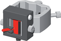
Rotor indicator: The pivoted rotor with reset pin uses a two-colour indication to inform the user of the state of the rotor indicator. “Black” means that the indicator has not been tripped whereas “red” indicates that the indicator has been tripped.
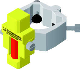
Fluid indicator: When a short-circuit occurs, the mixer is pulled up by the magnetic field stirring up red particles in the fluid. The indication resets automatically after six to eight hours once the red particles have set to the bottom of the mixer.
- Mechanical design
- Installation on cables or busbars
- Rotor indicator: fault indication by pivoted rotor
- Fluid indicator: fault indication by fluid with red coloured particles
- Retrofit ready
Your advantages
- Universal use
- Rotor indicator: reliable fault detection during re-energising
- Fluid indicator: automatic reset
- Maintenance-free, no battery
Technical specifications
| Earth fault detection methods | Earth short-circuit |
|---|---|
| Low-impedance/short-term low-impedance earthed | --- |
| Isolated earthed | - |
| Resonant earthed | - |
| Rotor indicator: Short-circuit trip current | 150 – 2,000 A (factory setting) |
| Fluid indicator: Short-circuit trip current | 400, 600, 1,000 A (factory setting) |
| Rotor indicator: Response delay short-circuit | 100 ms at rated trip value |
| Fluid indicator: Response delay short-circuit | 200 ms at rated trip value |
| Reset rotor indicator | Manual with hot stick |
| Reset fluid indicator | Automatic time reset: ca. 6 – 8 h |
| Housing | Housing and fixing screws made from polyamide Yoke made from ferromagnetic steel |
| Temperature range | -40 to +85 °C |
| Cable diameter | - |

