Short-circuit and earth fault indicators for underground cables
Short-circuit and earth fault indicators for underground cables
PASSION FOR PERFECTION
Intelligent local network stations play a central role in modern energy distribution. A particularly important element of these stations are the short-circuit and earth fault indicators, which contribute significantly to rapid fault detection and rectification.
What are short-circuit and earth fault indicators?
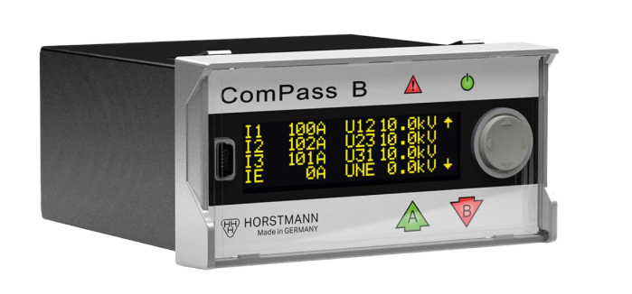
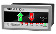
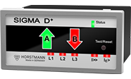
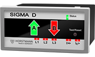
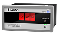
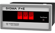
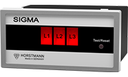
Short-circuit and earth fault indicators are essential components in modern power grids. They continuously monitor the current flow in medium-voltage cables and are specialized in detecting both short circuits between phases and earth faults. If a fault occurs, this is immediately signaled by visual displays on the station, by an LED or mechanical display. In addition, a remote message is sent to the network control center to enable a rapid response.
The mode of operation is based on the measurement of:
Phase currents for detecting short circuits
Phase current and residual current for identifying earth faults
Voltage drop to confirm fault detection
A particular strength of these indicators is their ability to differentiate between temporary and permanent faults. This prevents maintenance personnel from being called out unnecessarily in the event of temporary faults that correct themselves.
Integration into the grid control system is possible:
Immediate fault location
Faster resupply of customers
Reduction of downtimes
Documentation of error events for preventive maintenance
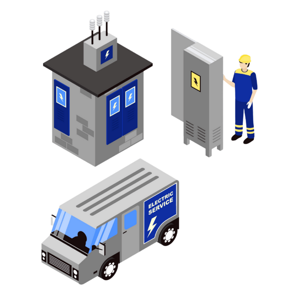
Intelligent local substations - energy supply for the future
Energy supply issues are not just issues relevant to the future. They are our questions and issues. And they include complex challenges at local grid substations, which we address with our innovative technical solutions. We are observing that of the estimated 600,000 existing traditional local network substations in Germany, the strategically most important stations, medium-voltage sections and regions are gradually being digitally expanded. Local grid stations are not only indispensable for the safe, efficient and uninterrupted distribution of electrical energy, but also form a key pillar for the digitalization of the energy supply.
We are the first port of call for switchgear manufacturers, station builders and grid operators when it comes to manufacturing high-quality products and system solutions for power distribution in the medium-voltage grid in order to make local grid stations digital.
We are aware that every minute counts for you as a distribution network operator in the event of a fault and that you need to find the causes as quickly as possible. The local grid stations digitized by us do this and deliver highly accurate measured values from deep within the grid to the control room during normal operation. This gives you an overview of grid utilization throughout the year at all times and also ensures effective and predictable load management.
Short-circuit and earth fault indicators & accessories from Horstmann at a glance
Fault location with network monitoring
Integration into a powerful grid control system enables precise fault location and ensures rapid action in the event of faults. In addition, continuous monitoring of the grid parameters ensures prompt feedback on the status of the electrical infrastructure.
With the directional indication, network operators can identify the exact position of the fault in the system. This facilitates the planning of necessary maintenance work and minimises downtime for end consumers.
Even without a direction indicator, the systems are able to detect faults efficiently. The general error message ensures that anomalies are detected quickly, even if the specific position cannot be detected.
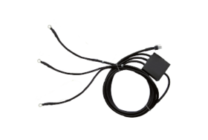
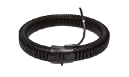
With integrated current and voltage sensors, the short-circuit and earth fault indicators are able to take continuous measurements and provide precise data. These sensors confirm fault detection and improve the reliability of the indicators.
Do you have any questions or would you like advice?
Would you like more details on a specific aspect of the short-circuit and earth fault indicators? Contact our sales team. We will be pleased to assist you.